How to find precise laser focus distance from surface
Lately, after long investigation, why ma laser is not working with the full power, I was forced to replace lens in it. You can read about the whole testing process here. Anyway, after I received spare lenses, and replaced it I started to wander if the focus distance has changed?
So far I was checking laser distance from surface with provided nylon blocks. I’ve also tested it once, by eye – checking how laser dot will change depending on the distance from surface, and I’ve assumed that provided spacers are close enough in size to use it regularly.
But now, I thought it’s time for more scientific approach.
So the idea is to measure the distance when laser is in focus, by checking it on long straight cut.
First of all we need to zero the laser – but now, instead of using spacers, we have to user laser itself – just like with all cutting bits on router etc.
Now if your laser has focus distance (manufacturer specification), like in my case 17mm, we can start from 10mm and finish on 20mm from surface. We just need to be sure to definitely start below and pass the focus point distance.
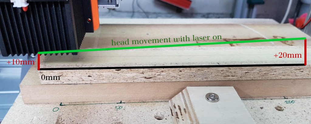
Next step is to raise the laser on 10mm distance from surface – this you should do manually, and then run the gcode that will move laser 200mm in X axis simultaneously rising Z axis by 10mm. We have to set the laser power as low as possible, so it will not burn when it’s out of focus.
The gcode will do a small dot on start and at the end and there should be burned line somewhere in between. If there is no line, check if the laser passes focus distance for sure and increase it’s power a bit. If the line is too long, or whole 20cm is burned, change laser decrease laser power in gcode.
S50 ; set high power (S) value here
M3 ; shot laser
G4 P0.5 ; for half a second
M2 ; turn off laser

S35 ; set low power (S) value here
M3
G91
G1 X200 Z10 F300 ; move 200mm on X and 10mm on Z with speed 300
M2

S50 ; set high power (S) value here
M3
G4 P0.5
M2
The provided gcode is very simple and you only need to modify S value. First S definition is for marking starting point, second definition is for proper testing and the last one is for final point. So first and third value should be high, so laser will leave the mark even if out of focus. The middle, proper one should be as low as possible.
I’m talking all the time about GRBL implementation of gcode – this can (and probably will be) a little different for other interpreters.
If you are not sure what value S can be – check you machine settings ($$) and see positions $30 and $31 – this are values for your minimal and maximum laser power (or to be precise, spindle min and max rotation 🙂 ).
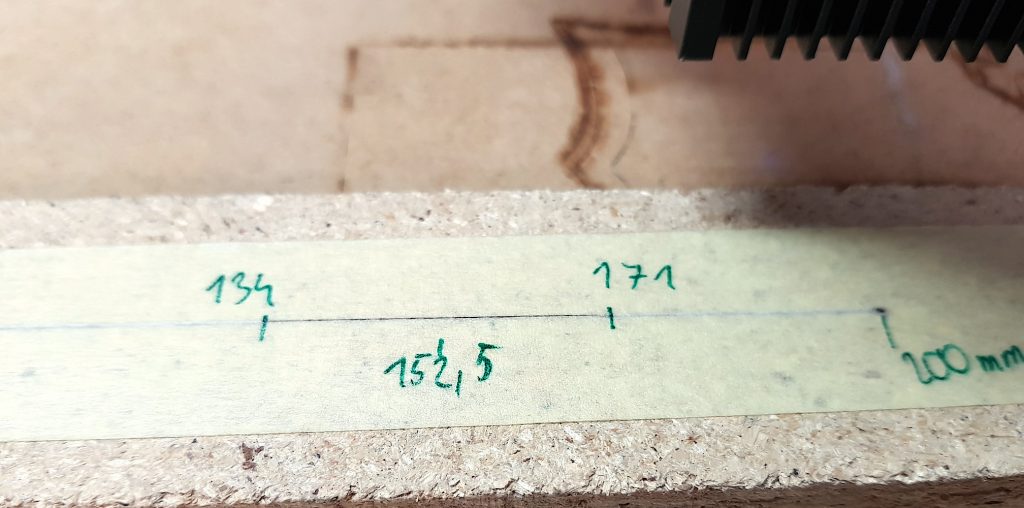
You can clearly see when the laser starts to burn the masking tape, and where it’s end. This region is what we are looking for. Assuming linear laser focus, middle of this line is our peak power of the focus.
Now I need to mark and measure where the burn starts and ends, calculate the middle of it and proportionally calculate the laser focus height.
For best results, you should lower power a bit even more (so the line will be shorter then on the picture above) and measure it twice or more.
(171+134)/2=152,5mm
(152,5/200)*10=7,625mm
10+7,625=17,625mm
In this example, middle of the burned zone is average of 134 and 171 mm – that is 152,5 mm. Proportionally on travel distance of 200mm this gives 0,7625 or 76,25% if you prefer. Because our vertical movement was 10mm, so calculated value (0,7625) times 10 gives 7,625mm. Now adding starting 10mm, we finally have peak power laser distance from surface, that is 17,625mm.