15W blue (450nm) LED laser module and GRBL investigation
 I’ve ordered, not so long ago, 15W laser module to replace my broken 5,5W one (5,5W laser was beeing replaced from factory). I was hoping to get much more power and be able to cut more… sadly it’s not that simple. It does not “engrave” on metal, does not cut deeper – so where is the problem? I’ll try to find out! 🙂
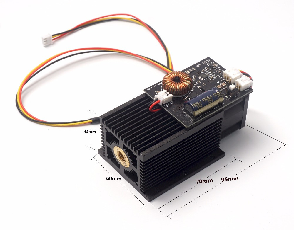
It seems like this 15W is only on paper, for marketing purpose. It’s called “impulse”, and we should be able to get peak power of impulse around 15W. Continuous power is 8W. I’ve ordered also module with fixed focus, not adjustable, since this type should offer better power transfer.
Browsing over different offers on Aliexpress, we can find some different specs. It should be powered with 12V DC (that is always the same), and peak power consumption should be 4-5A. Some other sellers claims it should drawn I <3A. All this can be true, probably some of them give current for power supply (12V) and other for laser module itself (it should be powered with constant current – but we can assume peak voltage somewhere near 5V). So 5V times 3A – yup, its 15W 🙂
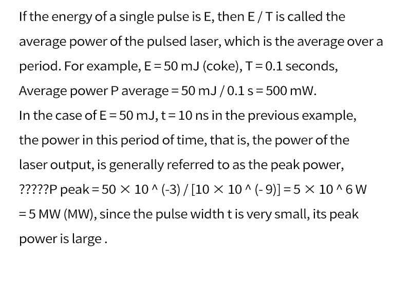
Another information we can find is TTL frequency (0-5V). Some sellers write it should be <9 kHz, and this is kind of true (you can read about it later). But some other (but to be fully accurate, with a bit different laser driver) claims it should be TTL <20Khz, and operation mode should be 100 ns pulses, with 50% duty cycle. And this is already suspicious since 100ns is equivalent of 10Mhz… something is certainly wrong here.

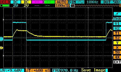 It looks quite ok. Square wave is sharp and we can see that driver reacts with some delay but is consistent with input signal.
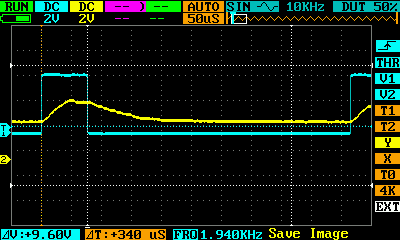
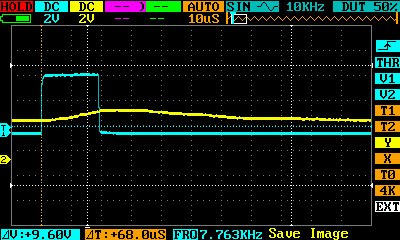
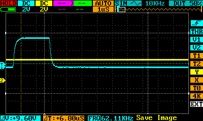
 // Prescaled, 8-bit Fast PWM mode.
#define SPINDLE_TCCRA_INIT_MASK ((1<<WGM20) | (1<<WGM21)) // Configures fast PWM mode.
// #define SPINDLE_TCCRB_INIT_MASK (1<<CS20) // Disable prescaler -> 62.5kHz
// #define SPINDLE_TCCRB_INIT_MASK (1<<CS21) // 1/8 prescaler -> 7.8kHz (Used in v0.9)
#define SPINDLE_TCCRB_INIT_MASK ((1<<CS21) | (1<<CS20)) // 1/32 prescaler -> 1.96kHz
// #define SPINDLE_TCCRB_INIT_MASK (1<<CS22) // 1/64 prescaler -> 0.98kHz (J-tech laser)
Back to the tests…
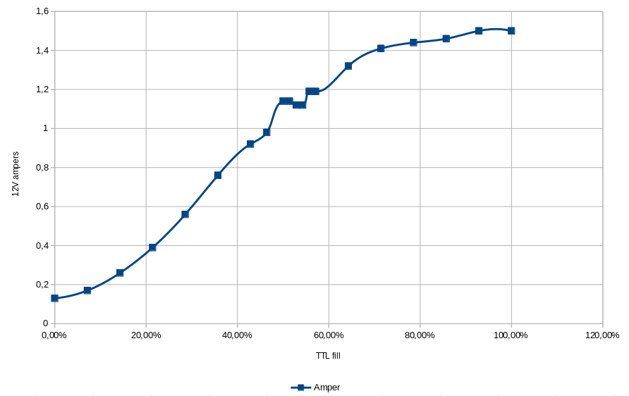 We can see here, that real power changes are up to 70% – later power changes are minimal. So when using laser to raster burning some photos, pictures etc. it’s best to use power values 10-70%. There is some strange thing going on around 50% power, that’s why I’ve took more samples. I don’t know why suddenly power is dropping down.
So the question still stands… why the laser in not etching the steel…
And btw. I’ve checked focus, It’s not as declared 18mm – more like 16mm but still – no luck.
Update 2019.01
So, just to let you know – It looks like the guilty part was the lens. I’m not sure if this lens get cloudy after some time of usage, or it was broken on production level, but I’ll probably know soon.
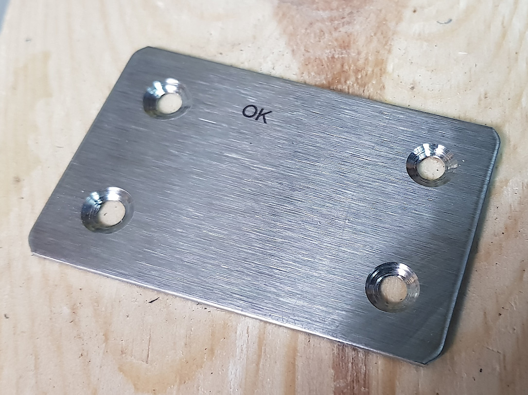
Anyway, after replacing the lens (I’v got 3 new from manufacturer – but not for free sadly) laser finally managed to etch something on stainless steel.
Hello, I really appreciate the info. I have a Woodpecker Arduino Uno with 1.1f grbl. I also bought an upgraded laser module, any information or suggestions you have on connecting the 3 wire module to PWM would be greatly appreciated. Thank you
I guess most, if not all, laser diode modules are 3 wires. 12V +/- and PWM signal. Where do you have a problem with connection?
I’ve encountered the same issue as jiminsandiego I think. My laser has 4 wires, I configured +12V,PWM,GND and not connected TEMP.
The Woodpecker 3.4 board just does not alter the PWM-pin other than 0.02V (=5/255). Enabled laser by
.
Did not yet set the max spindle speed @255, it’s still the (virtual) 10000 rpm of the spindle.
Will setting this 255 speed solve my problem, or am I missing some other thing here?
To have 5V PWM output you need to set grbl S value to 255 (or whatever you have under $30).
You can send commands like:
# $$ to see $30 value,
# then set spindle/laser to $30 value with S command (egx. S255)
# and start the laser M3 (constant power)
# disable laser with M2
This you can use without laser – just to measure voltage for PWM signal – after that you can connect the laser.
$33= 5000 ( this will give you 5kHz – for example) I know this will run on esp32_grbl and grbl-lpc, although when you’ll type: $$ usually this settings is omitted but on those two systems is registered correctly.
powodzenia