Makita 18V LXT Portable Power Station – howto
So recently I’ve switched to Makita 18V system. And I was a bit disappointed there was no something like DeWalt Power Station – that is 230V inverter powered with Makita batteries.
So like usually, I simply need to make one… cheap 😉
This gave me a bit of thinking, what voltage would be the best for this task. I’ve checked 12V and 24V, car inverters and sadly they all have over/under voltage protection that will not work with 18V Makita (that can vary from 20V to as low as 10V).
Then I’ve checked for 36V inverters, and there are some available, but the price is discouraging (like 300+ dollars) and they DIY version would be very bulky, since it requires large transformer (all custom/DIY are base on customizable Pure Sine Wave EGS002 board – you can watch more about it on Great Scott channel, but beware, there are mistakes in this video – read comments).
So back to car inverters… that are cheaper (like 50$) and more useful in other situations like car/camping, then 36V solution.
I could step up voltage to 24V or step it down to around 12-13V (later I’ll write why). Since 12V inverter will be more useful to me, because I can also use it at my car, I’ve decided to go for step down.
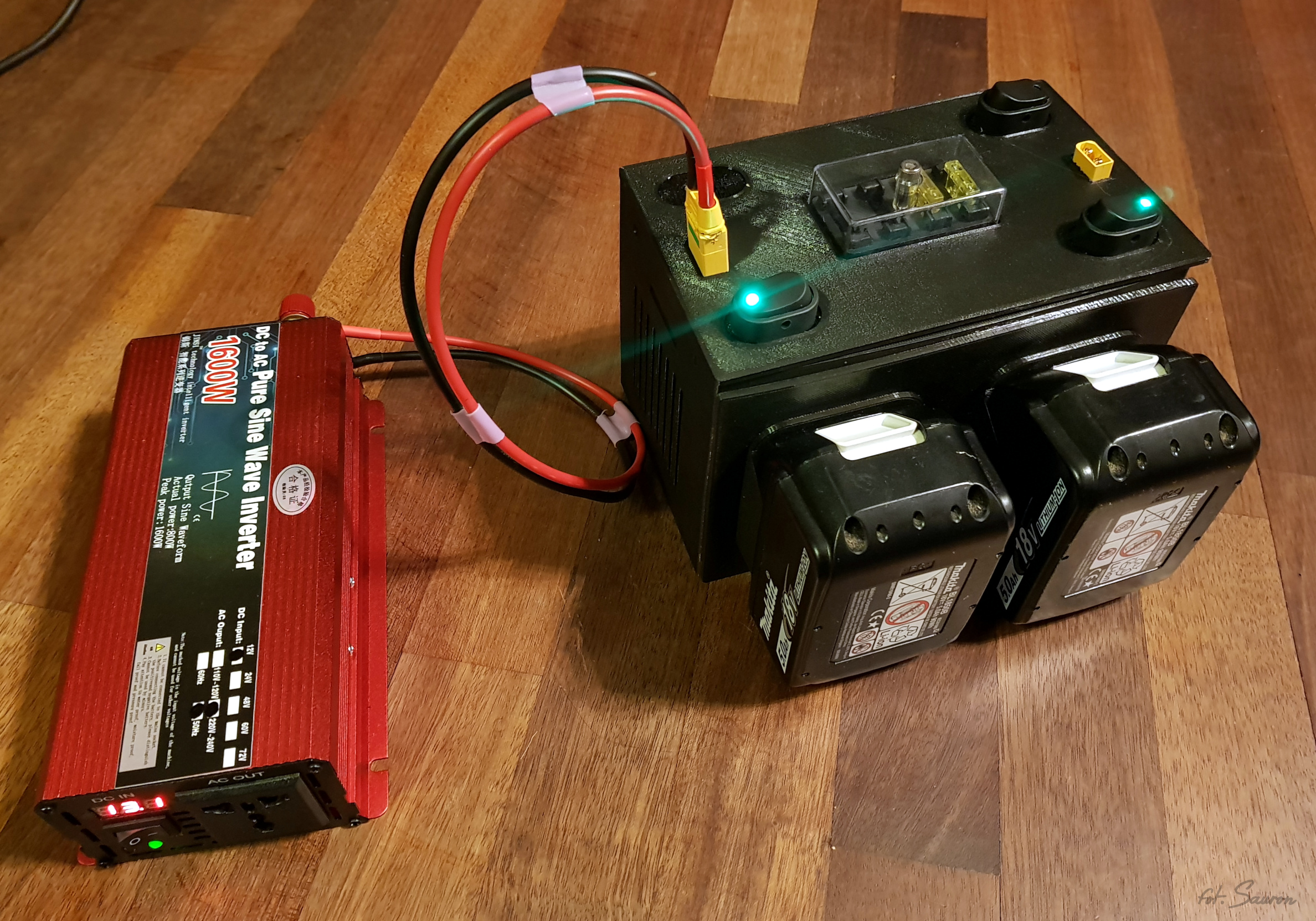
I’ve ordered 800W pure sinewave inverter (peak power 1600W) for around 50 USD shipped. I don’t think anything more will be useful for this type of power source, or even with the car battery.
If you would go with 24V and want to use inverter later on, for some kind of the off grid system – you could use more robust device – this won’t hurt batteries if you will limit power usage to something sensible.
800W inverter still requires at least 67Amps (more like 80A) for 12V and this is already a lot of current (twice at peak). For large car batteries it’s not something terrible (my 100Ah battery has peak current over 800A) – but it could drain it real fast, and four Makita batteries in a blink of an eye.
Actually let’s do some calculation here. Makita 5Ah battery will give us roughly 90Wh, times four it’s 360Wh. Assuming 85% (I’m guessing here – but based on some experience) step down efficiency. This will give us 360Wh*0,85 = 306Wh, I’ll make it 310Wh. Now again, assuming efficiency of the inverter at 80% (this is wild guess – I don’t know that). We have 248Wh. So finally for 800W load, we should get around 18minutes of run on four batteries, two will give us only 9 minutes. And this is still much more, then we will get in real life, because of buck converter voltage drop limit (more – later), battery discharge efficiency under heavy load etc.
Anyway, I assume Makita batteries (5Ah or more) can provide 20A current easily. I haven’t tested more, but quality 18650 cells are usually rated 20A-30A. There can be some limitation for electronics inside battery – so 20A is my limit.
I’ve ordered two DC-DC step down boards, that are rated for 300W (20A) – but it’s “Chinese” 300W, so more like 200W or even less. Judging by the components used, I was surprised it handled 10A that well 🙂
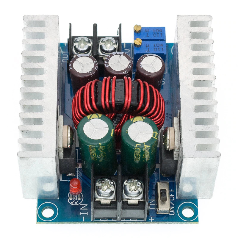
Recommended load is 15A (small print), so around 180W. I’ve prepared additional cooling, so I guess it should manage to go to 20A peak at 13V (240W-250W).
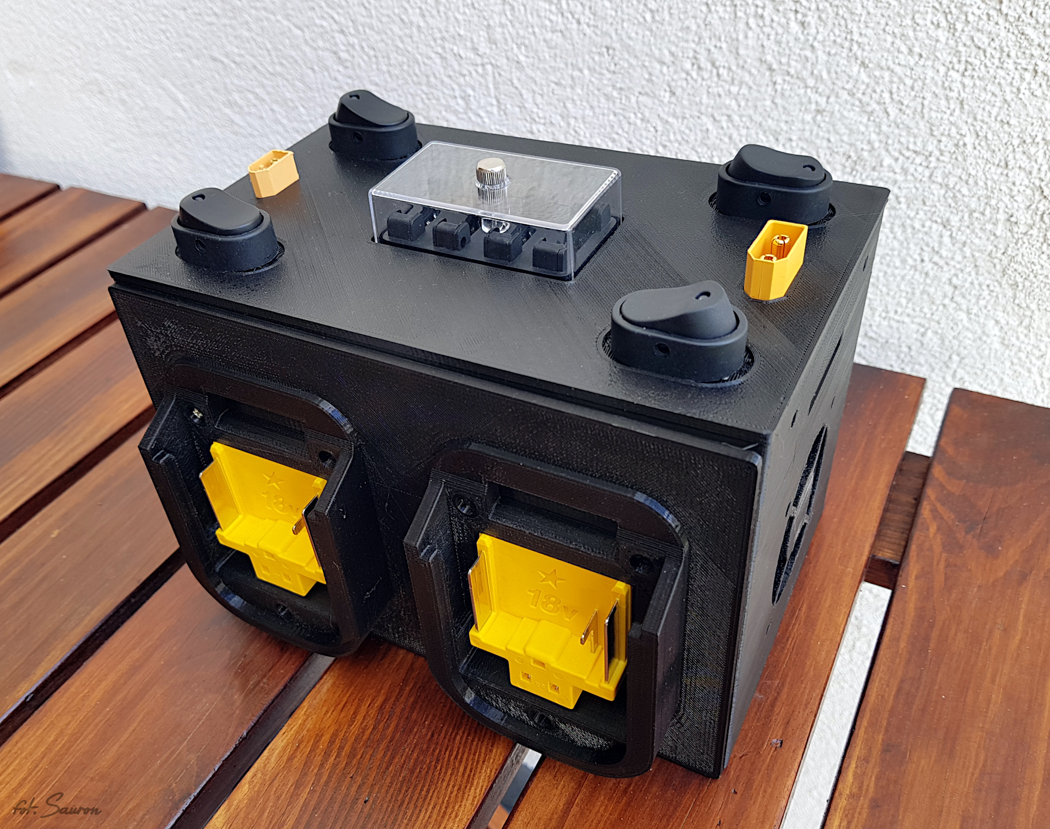
After some tests, I’ve ordered two more buck converters and prepared printable case for entire device. In general it’s large and quite powerful 12V power supply, that can be extended with 12V inverter (up to you if it’s going to be 230V or 110V).
Single battery – 15-20A, two batteries 30-40A, three 45-55A and four 60-80A.
Printable version of battery holder and the box itself I’ve put on Thigiverse.
Required components:
- 1 or more step down (buck) converters to change 18V (20V) to 12V
- 1+ Makita battery connectors – you could also print it. I’ve manage to find genuine parts in Poland for 2EUR
- 1+ Schottky diode – 25V+ 20A+ (I’ve used 20SQ045 – 45V, 20A – bigger would be better, this is what I had at hand)
- 60x60mm 12V fan
- XT90 connector – to connect battery pack to inverter, I’ve also add smaller XT60 connector, because I have quite a lot of DIY devices with that connector.
- Optionally (but recommended) breaker box with 20A – 25A fuses per line
- Four switches – mine proved to be too crappy – one broke and short circuit the battery melting the wires – needed to replace them later
- For aggregated current lines use 10mm2 wires (at least 6mm2), for battery->switch->fuse->buck converter->aggregator 4mm2 wires will be sufficient.
- To connect battery holders with the box itself, you should have some M3, 10mm (perfect length – can be longer) long bolts and nuts
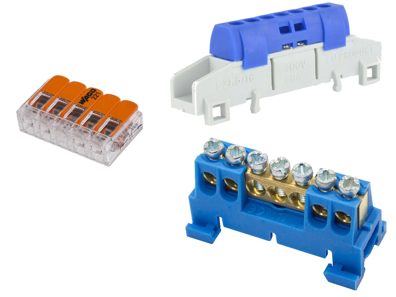
- As an aggregator you could use Wago (left on picture above) connectors (they should withstand the current, despite they are not rated for it) – but I’ve used connector (two on the right side of the picture above) design to be used in mains line boxes rated for 80A.
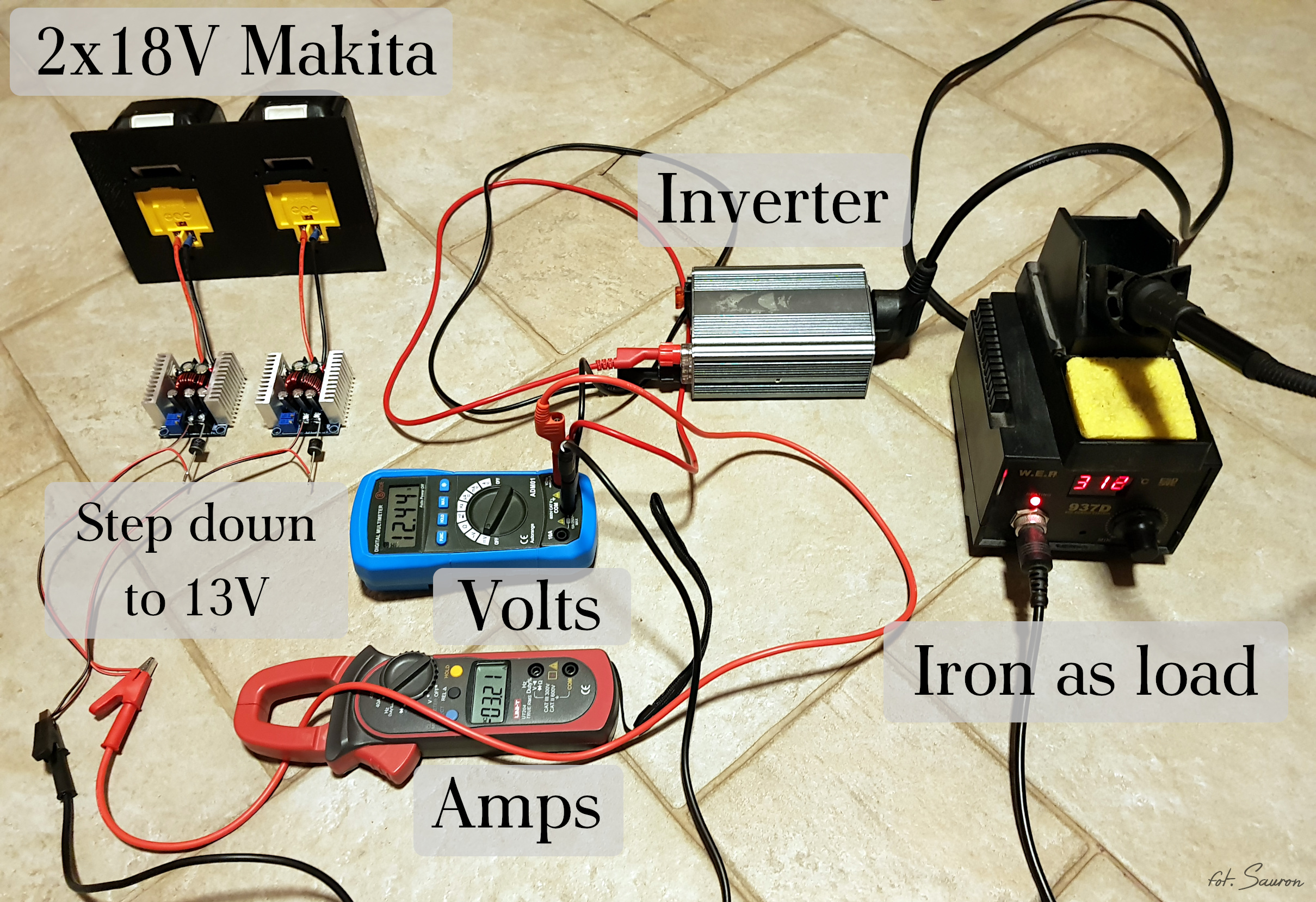
Connecting is quite simple:
You can help yourself with the picture on the top, where there is everything lying on the floor and described components. Just add switch and breaker box.
- connect battery connector positive line to switch (if you have it with diode – like I do – you also need to provide negative/ground one)
- connect positive line from switch to breaker box
- connect negative line from switch and positive from breaker box to buck converter input terminals
- add diode on positive output of buck converter and connect positive and negative lines to aggregator
- connect aggregator positive and negative lines to XT90 socket, and create additional cable with XT90 plug and loop connectors for inverter
- You should also try to, as precise as you can, set up every step down converter to the same voltage levels.
Now few words about set voltage on buck converters. Since they are step down devices, they cannot operate if the source has lower voltage then set voltage. I did some testing, and Makita batteries are setup in quite destructive way – over discharge protection is set around 8V. This is much too low for most of the Li-Ion cells – 8V/5 (5 cells) = 1,6V per cell. Haven’t check what cells Makita uses, but one of the best Sony VP6 should not be discharged to less then to 2,5V. So Makita batteries when deep discharged, are unrecoverable damaged and loose capacity. This is probably, because they wanted to squeeze as much Wh as they could, from battery – and did not care about lifetime.
Anyway, since Inverters usually have overdischarge protection set for lead acid batteries on around 10,5V – and since we need to add at least 1V for buck converter – this is not the case here. Even if we set the output of buck converter as low as 11V – they will stop working when Makita batteries reach around 12-12,5V (2,4V per cell). And I don’t recommend to set it that low, because there will be some power spikes that can trigger inverter protection by lowering voltage below 9,5V. So something safe to set on step down converters is 12V.
Because those DC-DC converters are both CV and CC – mine came with CC set around 10-11A. So you should set it up to around 20A – this will be a lot of twisting :). Both Constant Voltage and Constant Current trimmers when turning clockwise increase it’s limit, counter clockwise decrease it.
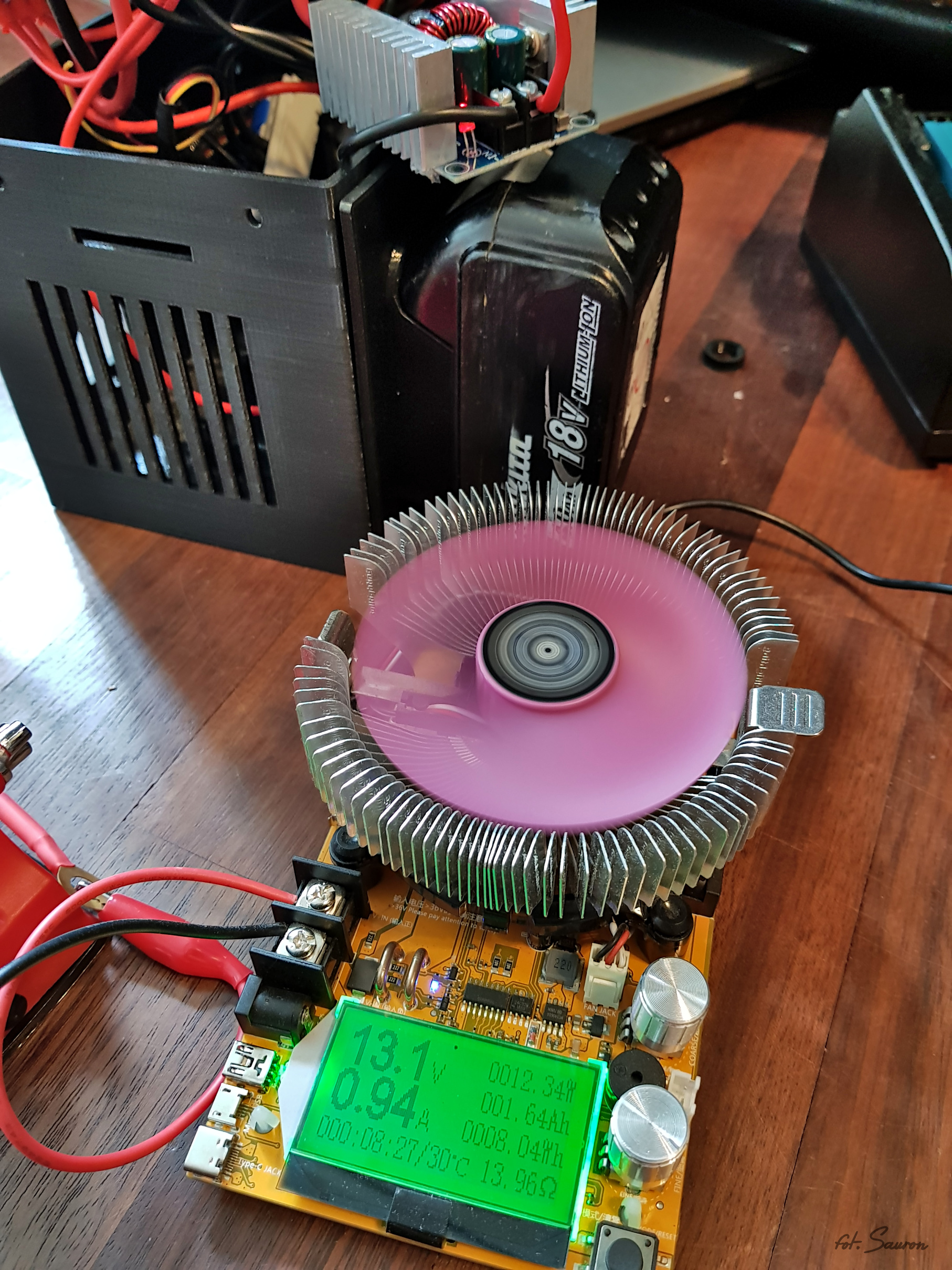
Since my load is able only to withstand 150W – I was unable to set 20A@13V at DC-DC converter, but I’ve just lowered voltage to 5V and then I could set 20A on load.
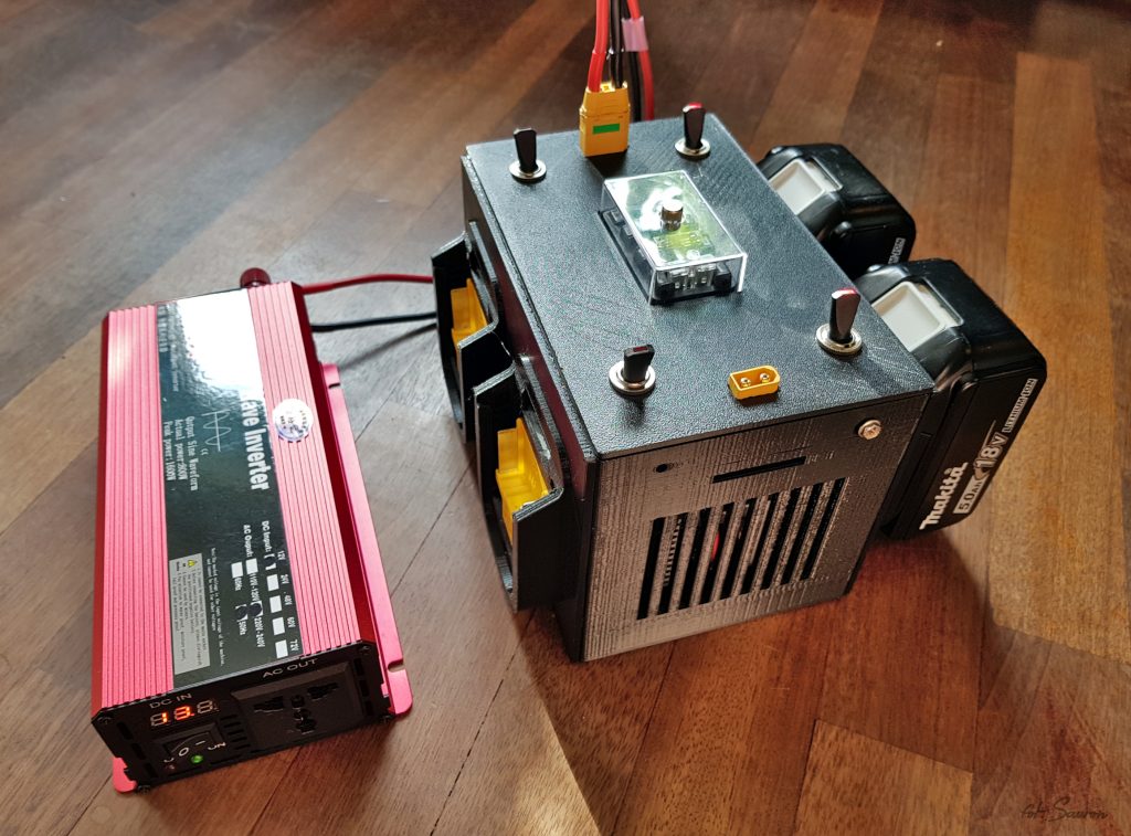
Fully working device, printed in PETG with new 30A switches and new cable. 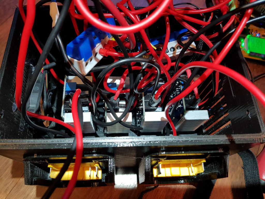
Inside the device – all four buck boards. Yet without the spacer bars.

Some final words. I’ve tested this device under long term load (like 200W) for 2 hours continuously – I haven’t observed any problems. I’ve tested it for few minutes with around 800-900W load (meter showed almost 90Amps on output) – all wires and electronic was fine. But of course, main wires were getting hot. So I can say this device is definitely working.
But it’s also not without problems. I’ve noticed that batteries are not discharged evenly. I was expecting that – because of not perfect DC-DC buck converters and even voltage output setup. I haven’t notice it to be a real problem – it balanced itself during longer usage and finally all batteries where evenly discharged :).
very cool project
Hello.
It’s a cool project you have here.
I have a question. Why do you have a switch for each battery?
Greetings Peter from Denmark
Hi, simple – otherwise it would draw power from the batteries all the time – even when it’s not used. Of course you could remove batteries – but it’s also convenient as a battery carrier/holder 🙂
Thanks for reply.
Is it the step down (buck) that draw power?