MKS Gen 1.4 board with TMC2130 and Marlin firmware – howto
 I wanted to change my Infitary HiB3 stepstick drivers with TMC2130, mostly to get it working more quietly but also because the perspective (meaby someday…) of other nice features of Prusa i3 MK3 where appealing. Sadly Infitary has all motor drivers SMD soldered so I had to get everything new. I ordered (what seems to be the best value-money choice) Chinese MKS 1.4 board and pack of 5 TMC2130 v1.1 stepper drivers. The only difference (except the price ;)) between Chinese 1.0 and 1.1 TMC stepsticks is that 1.0 are soldered to be used without SPI feedback data. You could change them manually from 1.0 to 1.1 (you would need to resolder 3 jumpers and change side of 4 connectors – see picture), but I assumed it’s too much hassle and I went with 1.1 directly
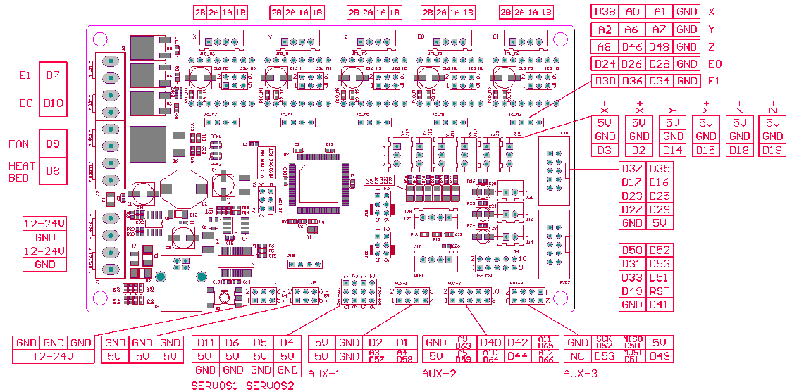
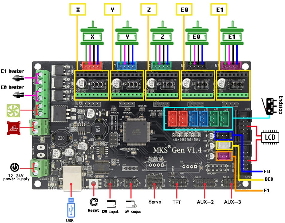 The MKS 1.4 board is a simple ATmega2560 board with RAMPs 1.4 compatible connectors. It’s nice all-in-one solution, with almost everything you could possibly need for cheap 3d printer and a bit more:
- You can power it up with 12-24V power supply,
- you can have 3 axis drivers, 1 extruder driver and optionally additional extruder or axis driver. In my case, I have 2 Z-axis steppers so the E1 is going to be Z2. I could go with (like in my previous board) one Z-axis driver powering two steppers, but it’s rather ugly solution and since we want to have some “intelligence” out of our TMC drivers – this wouldn’t work well.
- it has all endstops, fan and heated bed connectors,
- two LCD connectors and
- and two AUX ports.
Let’s begin…
 I’ve used TMC drivers for all stepper motors, you could save some money and use it only for X/Y axis (perhaps Z) – but I ordered set of 5, and used all 5. I also used TMC 2130 feature to eliminate X and Y endstops (I still have mechanical Z min. endstop). Finally I have LCD with SD card reader – this is important, since I had to change pins 53 and 49 from “default” configuration (like for example Tom presented) to utilize unused endstops pins, to be able to use SD card still. I’ve also wanted to use interrupts for every working endstop (for ATMEGA this are 2, 3, 18, 19, 20, 21) – so there are also some small changes from original setup.
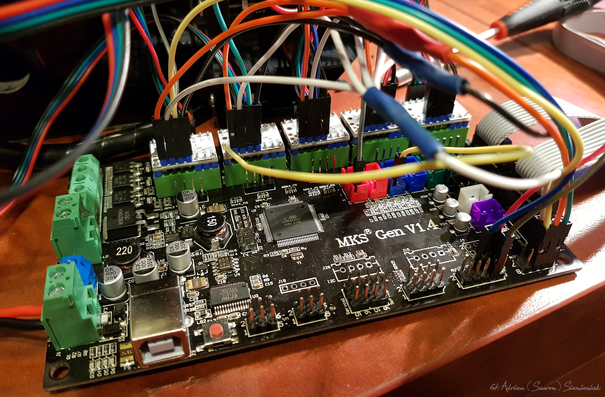
- Remove all jumpers, that are going to be under TMC2130 driver (this could make you a lot of weird troubles if you forget 😉 )
- Put driver boards in place, remembering about correct orientation (match descriptions on MKS board with those on TMC board) – in my case, SPI pins where on green side (lower one)
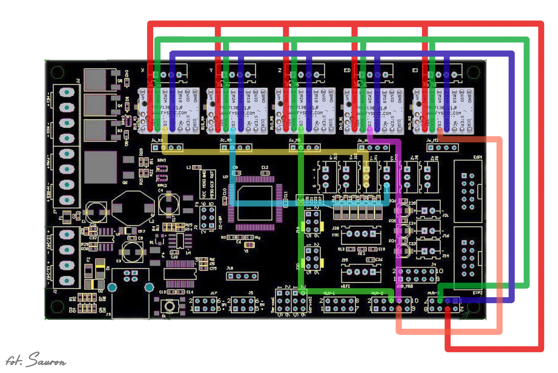
- Connect 3 common lines from every driver to pins on AUX 3 socket (SPI connection schema). I’ve prepared for myself, 3 cables with 6 connectors each soldered together
- Connect CS line from every TMC driver to different pin on the MKS Board – pins from X and Y TMC drivers are connected to endstop pins, so SD card reader could work 🙂
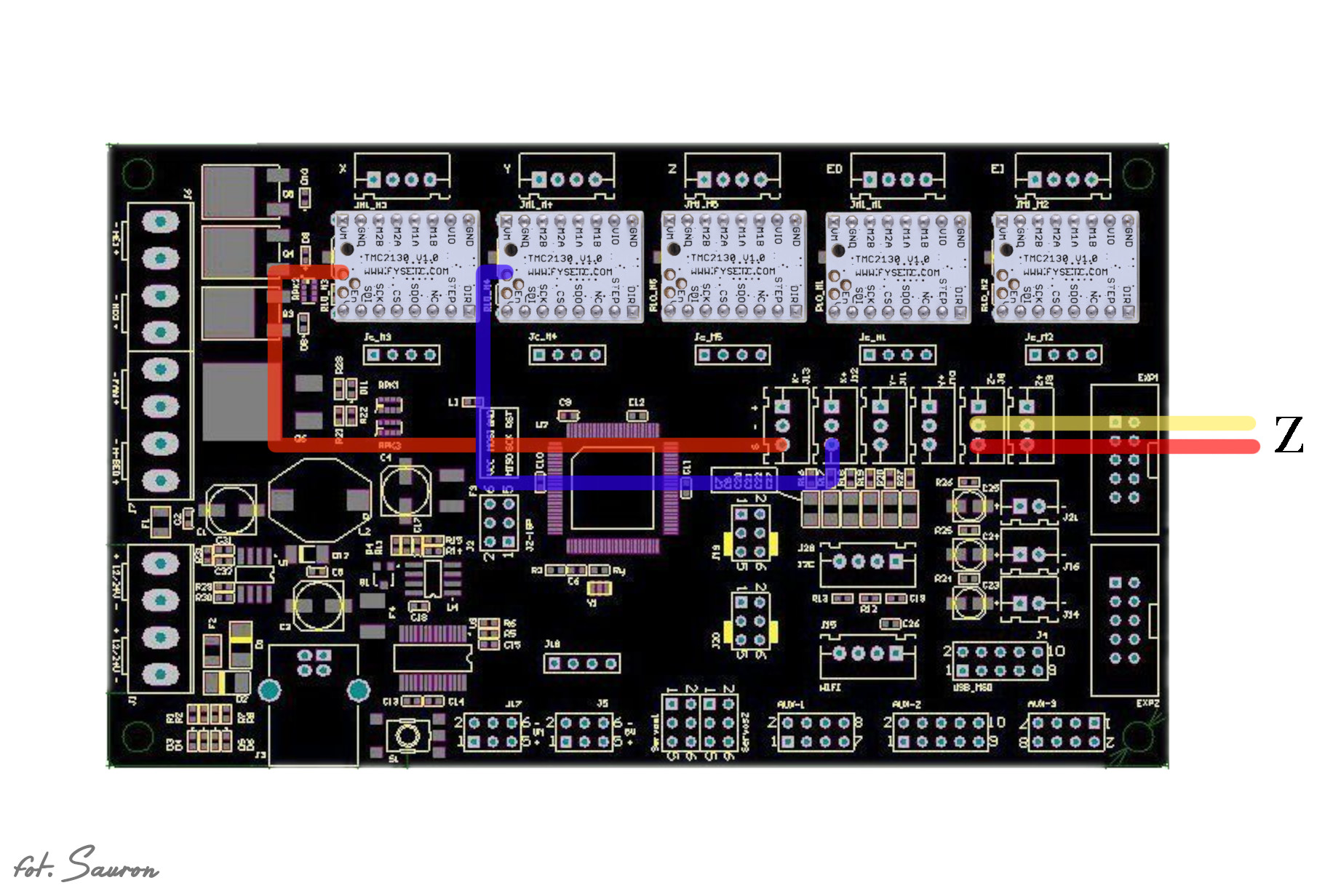
- Connect X and Y TMC endstop signal to X min and X max endstop pins (this is also different, because we want to use interrupts – respectively pins 2 and 3)
Now the software…
- do a clone of git bugfix repo (“git clone -b bugfix-1.1.x https://github.com/MarlinFirmware/Marlin“)
- add TMC library to Arduino IDE. Choose from “Sketch” menu, “Include library” -> “Manage library” and search “TMC2130Stepper”
- You have to edit those files
- Configuration.h
- Configuration_adv.h
- pins_RAMPS.h
Warning! This are only steps that are somehow different from standard configuration. Unless you’ve downloaded prepared config, you have to do other changes for your printer!
Configuration.h
Define board:
// The following define selects which electronics board you have.
// Please choose the name from boards.h that matches your setup
#ifndef MOTHERBOARD
 #define MOTHERBOARD BOARD_MKS_13
#endif
Define endstops (X and Y are TMC – so they can work on both ends – min and max. Z is traditional, so only min):
// Specify here all the endstop connectors that are connected to any endstop or probe.
// Almost all printers will be using one per axis. Probes will use one or more of the
// extra connectors. Leave undefined any used for non-endstop and non-probe purposes.
#define USE_XMIN_PLUG
#define USE_YMIN_PLUG
#define USE_ZMIN_PLUG
#define USE_XMAX_PLUG
#define USE_YMAX_PLUG
//#define USE_ZMAX_PLUG
Enable interrupts for endstops:
// Enable this feature if all enabled endstop pins are interrupt-capable.
// This will remove the need to poll the interrupt pins, saving many CPU cycles.
#define ENDSTOP_INTERRUPTS_FEATURE
Configuration_adv.h
Just speeds up homing – move X/Y at once:
#define QUICK_HOME // If homing includes X and Y, do a diagonal move initially
Enable TMC 2130 support:
/**
 * Enable this for SilentStepStick Trinamic TMC2130 SPI-configurable stepper drivers.
 *
 * You'll also need the TMC2130Stepper Arduino library
 * (https://github.com/teemuatlut/TMC2130Stepper).
 *
 * To use TMC2130 stepper drivers in SPI mode connect your SPI pins to
 * the hardware SPI interface on your board and define the required CS pins
 * in your `pins_MYBOARD.h` file. (e.g., RAMPS 1.4 uses AUX3 pins `X_CS_PIN 53`, `Y_CS_PIN 49`, etc.).
 * You may also use software SPI if you wish to use general purpose IO pins.
 */
#define HAVE_TMC2130
Enable wherever you have TMC 2130:
#if ENABLED(HAVE_TMC2130) || ENABLED(HAVE_TMC2208)

// CHOOSE YOUR MOTORS HERE, THIS IS MANDATORY
#define X_IS_TMC2130
//#define X2_IS_TMC2130
#define Y_IS_TMC2130
//#define Y2_IS_TMC2130
#define Z_IS_TMC2130
#define Z2_IS_TMC2130
#define E0_IS_TMC2130
//#define E1_IS_TMC2130
//#define E2_IS_TMC2130
Enable SPI for TMC:
 /**
 * Monitor Trinamic TMC2130 and TMC2208 drivers for error conditions,
 * like overtemperature and short to ground. TMC2208 requires hardware serial.
 * In the case of overtemperature Marlin can decrease the driver current until error condition clears.
 * Other detected conditions can be used to stop the current print.
 * Relevant g-codes:
 * M906 - Set or get motor current in milliamps using axis codes X, Y, Z, E. Report values if no axis codes given.
 * M911 - Report stepper driver overtemperature pre-warn condition.
 * M912 - Clear stepper driver overtemperature pre-warn condition flag.
 * M122 S0/1 - Report driver parameters (Requires TMC_DEBUG)
 */
 #define MONITOR_DRIVER_STATUS
Enable endstops:
 /**
 * Use stallGuard2 to sense an obstacle and trigger an endstop.
 * You need to place a wire from the driver's DIAG1 pin to the X/Y endstop pin.
 * X, Y, and Z homing will always be done in spreadCycle mode.
 *
 * X/Y/Z_HOMING_SENSITIVITY is used for tuning the trigger sensitivity.
 * Higher values make the system LESS sensitive.
 * Lower value make the system MORE sensitive.
 * Too low values can lead to false positives, while too high values will collide the axis without triggering.
 * It is advised to set X/Y/Z_HOME_BUMP_MM to 0.
 * M914 X/Y/Z to live tune the setting
 */

 #define SENSORLESS_HOMING // TMC2130 only
pins_RAMPS.h
//
// Limit Switches
//
#define X_MIN_PIN 3
#ifndef X_MAX_PIN
 #define X_MAX_PIN 3
// #define X_MAX_PIN 2
#endif
//#define Y_MIN_PIN 14
#define Y_MIN_PIN 2
#define Y_MAX_PIN 2
//#define Y_MAX_PIN 15
#define Z_MIN_PIN 18
#define Z_MAX_PIN 19
//
// Steppers
//
#define X_STEP_PIN 54
#define X_DIR_PIN 55
#define X_ENABLE_PIN 38
#ifndef X_CS_PIN
 #define X_CS_PIN 14 // Z Y_MIN_PIN
// #define X_CS_PIN 53
#endif

#define Y_STEP_PIN 60
#define Y_DIR_PIN 61
#define Y_ENABLE_PIN 56
#ifndef Y_CS_PIN
 #define Y_CS_PIN 15 // Z Y_MAX_PIN
// #define Y_CS_PIN 49
#endif
Your endstop connection is wrong. You got Y axis endstop on X_Max end stop 🙂
It’s not wrong, please read what I’ve changed to enable interrupts and SD card. I’ve remapped those pins in pins_RAMPS.h 🙂
I guess, what he says is that in the picture “SPI Connection” You connect the Y and X endstops to the Y MIN and Y MAX, but you say it has to go to X MIN and X MAX, as shown in the picture above.
Im following your tutorial, excellent!
You are right, description (with X MIN/X MAX) is wrong – corrected!
I think that you were correct the first time. The lines going to Y MIN and Y MAX are chip selects, not endstops, right?
Are the connections the same for a MKS Gen L 1.0?
Also could I use E2 to drive my Z2 stepper and could both Z steppers have sensorless homing to make sure the gantry is parallel to the bed?
I meant use the E1 to drive my Z2 stepper.
Connection should be close if not identical – you can compare pin layout for both boards on schematic. If board can handle second extruder, then yes – you can change it to second Z axis motor (motor for axis and extruder are the same type – and controller don’t care if it moves filament or axis).
To do something similar to Prusa Mk3 Z axis levelling (triggering Z max on both steppers individually) should be possible – my construction is not sturdy enough, so I haven’t tested it… yet 😉
I’ve managed to make it work, thanks for your help ! I don’t know why, but when i had the move the SCO wire from the D50 pin to D64. When connected to D50, my TFT32 display couldn’t communicate with the board. So I moved it to D64 and change the pin location in “pins_RAMPS.h” is that ok ? #if ENABLED(TMC_USE_SW_SPI) #ifndef TMC_SW_MOSI #define TMC_SW_MOSI 51 #endif #ifndef TMC_SW_MISO #define TMC_SW_MISO 64 #endif #ifndef TMC_SW_SCK #define TMC_SW_SCK 52 #endif #endif Also I have a filament sensor with 3 pins (5v+,GND,SIG) on which pin shouldI connect it? I’ve read that I… Read more »
Well, D50 is connected to EXP1 socket – so potentially LCD can use it (in my case (MKS_MINI_12864) it’s assigned to beeper and I don’t have it).
So you can reassign it to any other, free digital pin.
TFT32 has it’s own driver (that serializes connection with ATmega) – so I don’t know how it will work this way.
By default FIL_RUNOUT_PIN in defined in pins_RAMPS.h on pin D4 – this pin is available in servo socket.
I get:
Driver registers:
X = 0xE0:0C:00:00
Y = 0xE0:0C:00:00
Z = 0xE0:0C:00:00
E0 = 0xC0:0C:00:00
E1 = 0xE0:0C:00:00
Some have the same address, is this correct?
Yes, it’s ok (if this is truly correct, this is completely other case) – I also have the same registers. Even in examples in marlinfw you can see the same addresses: http://marlinfw.org/docs/gcode/M122.html
I had to resolder the connections on the board. The problem is that if I plug the driver in, it starts heating up immedialty without anything else connected on the board. What did I do wrong?
You would have to show some schematics, pictures – it’s hard to tell with information you provided so far. If it’s heating, it means it transfers current (close circuit), did you insert it correctly?
What can i do if i don’t can solder those 2 tiny spots? ( i manage to remove the resistor but i fail to make the other two)
I assume you are talking about TMC2130 board and changing it to SPI aware version (1.3). There is no other way (except buying new) then to resolder those tiny pads. Just use magnifying glasses and good, pointy soldering iron. To clean pads from solder, use some soldering copper wick.
I may be late to the party but i have one Question. You said you got SD Card to work, how is that?
I Only (visible) Plan on using a MKS TFT32, do you have plugged in another Display/SD Card Reader Combo?
Do you know of anything that would work for me?
Yes I have working SD card reader, but like I wrote it comment above, TFT32 is completely different beast. I haven’t used it, but as far I read specs, it uses own protocol to communicate with printer board and it’s computer by itself (has own firmware etc).
I used so far two displays – RepRapDiscount Smart Controller and currently MKS MINI 12864 – on both, sd card was working.
Thank you soooo much for this tuto, it really helped me. finally have my TMC’s running, but i still have a problem. Z mechanic end/stop works fine, but X/Y don’t, and i don’t really care to continue using mechanic ones, what should i change on Marlin to continue using mechanical end stops on X/Y?
This is a copy of my answer from YT video: If by “don’t move” you mean it hit’s endstop (see console output) you probably just need to invert those endstop status in config file. This is my current configuration – like you can see Z (mechanical) is not inverted (false). Just make X/Y also not inverted and try. // Mechanical endstop with COM to ground and NC to Signal uses "false" here (most common setup). #define X_MIN_ENDSTOP_INVERTING true // set to true to invert the logic of the endstop. #define Y_MIN_ENDSTOP_INVERTING true // set to true to invert the logic… Read more »
Hi. I am finishing my 3D printer built from scratch. It is a CR-10 clone. I have installed TMC2130 stepper drivers on a MKS Gen 1.4 board. I have all the TMC2130´s in the V1.0 version that is supposed they will not work in SPI mode. Is this a problem? Do I need to follow your Marlin config.h and config_adv.h respecting my machine dimensions, stepper motors specs and so one? What should be a reasonable voltage for the stepper drivers? Thanks for your job supporting the community . They help us a lot. Silvio. Cheers from Brazil.
Hi Silvio. Without connected SPI (you have SPI on your steppers – it’s just simply not connected out and not configured – but this information is already in article) you are missing few additional features like: General Configuration Registers global configuration global status flags interface configuration and I/O signal configuration Velocity Dependent Driver Feature Control Register Set driver current control setting thresholds for coolStep operation setting thresholds for different chopper modes setting thresholds for dcStep operation Motor Driver Register Set setting/reading out microstep table and counter chopper and driver configuration coolStep and stallGuard2 configuration dcStep configuration reading out stallGuard2 values… Read more »
Hello , Thanks for this tutorial
i Have Buy MKS Gen 1.4 And Driver TMC 2310 SPI So the connection That u explain on this tut that is will connect to my board ?!
i Have Question Of in connection Driver X And Y to End Stop !
How i can Do it .. i can see in photo u take the 3rd Hole in back of driver to end stop How i can do this ?!
In this configuration can I use the original lcd display of the anet? Which memory card reader should I buy? Thank you!
Thanks for this explanation, but I still don’t get the end stops part.
I do understand for interrupt based end stops. But where do you hook up the end stops now? Like I mean the switches themselves?
In this configuration physical switch is used only for Z MIN endstop. X and Y MIN/MAX are from TMC controllers. How to connect both is on presented on “Endstop connections” picture.
Edited, but how does the board know when it hit the xy limits?
I’m still building my printer, and I was thinking: I need 2 stops per axis. But out of this I understand, you only use the z?
This is feature of TMC drivers – since motor cannot move anymore (hit’s the frame) it dawns more current, this is something that driver can measure and it knows you have hit virtual “endstop”. This works for X/Y – since there is frame.
For Z you usually have to stop before the lowest part of the printer – and you should be able to change that level according to your bed level – that’s why there is physical switch to detect Z min.
Oooh that’s actually quite interesting. Hmm but that gives me a tiny problem. As I’m building my printer, my xy limits have a bit of space, but I guess I can block that. A thing easily done, esp now I know the theory around it
With the new firmwares available it seems they removed support for TMC drivers for: “ENDSTOP_INTERRUPTS_FEATURE” are you aware of this? Is there a fix? Or should I just go back to your firmware?
Last time I’ve checked it was still there (end of December).
// Enable this feature if all enabled endstop pins are interrupt-capable.

// This will remove the need to poll the interrupt pins, saving many CPU cycles.

#define ENDSTOP_INTERRUPTS_FEATURE
yeh it’s still there, but when you uncomment that for TMC drivers:
TMCStepper includes SoftwareSerial.h which is incompatible with ENDSTOP_INTERRUPTS_FEATURE. Disable ENDSTOP_INTERRUPTS_FEATURE to continue.so can’t compile.. is that feature really needed or will it still not stop on software checking? (’cause as far as I understand it without that define it will just poll the interface)
It has nothing to do with TMC, but it may with the board you are using. Are use compiling Marlin 1.1.x or 2.x ?
You can disable HW interupts – it will then check status periodically. This should have not a bit impact when used only during homing.
I have a MKS Gen v1.4 and using 2.x . I learned from google that it’s a fairly common problem and some speak of being able to just disable sanity checks, but I haven’t heard any successtories yet.
Above guide is for Marlin 1.1.x – not for 2.x.
Yeh, I used your “Or you can download what I’ve prepared 🙂”. I’m assuming 1.1.x isn’t too much of a downgrade to 2.x? Btw that download, you changed the values for the Limit switches, but not the steppers xD was wondering why it gave me a short on one of the steppers. Sooo I changed a few things, now my screen is working, steppers are working. Tho, perhaps you know this: I’m using 2 Z steppers, you use 2 drivers but I’m using a board that splits the 1 driver. But now they turn 1/2 as fast. Which makes sense..… Read more »
Hi
just a little comment: enabling “#define SOFTWARE_DRIVER_ENABLE” will cause NO movement in using TMC2130.
Hello, can you offer advice on issue with Ender black widow , motors not working, I think wiring issues
Hi can you make a tutorial for marlin 2.0. i am scratching my head for dual z axis to work.