Engraving, cutting 5.5W laser – description and proper connection
 During upgrading my engraving machine (Chinese so called CNC 3018) I had to do some reverse engineering to do proper connection. Perhaps someone else may find this information useful – so here you go 🙂
Laser itself is distributed as two part set. Laser in aluminium cooling block with fan (and four wires), and PWM/TTL controller board.
Controller board uses this main components:
- XL4003E1 – voltage regulator with input voltage 5V-32V, 4A CC max with 300kHz switching frequency
- IC chip MCP60021 OPAMP – operational amplifier
- Voltage regulator 78L05 – 5V output, 100mA
- NPN transistor D476 61C
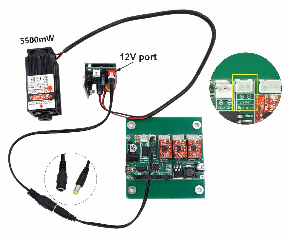
Chinese CNC machine is to be connected quite awkwardly to controller board (picture on the left), because this way it do not send pulse (PWM 0-5V) signal from pin 11 of Arduino to PCB along with 12V power supply – like it should be done. Instead of it, Woodpecker board do PWM on its own (the same line as for spindle motor) and sends PWM 0-12V signal to laser controller. There from the same PWM voltage we have to power both laser and fan (???). So instead of 255 PWM states of laser we have a lot less, just few.
This is probably because manufacturer did not want to do different connection for every type of laser (they sell 0,5W 1W 2,5W and 5,5W lasers). But this is even more surprising, since newer Woodpecker (still marked as 0.9) boards have directly available pin 11 on lower connector lane (instead of one of the Z endstops connection).