PIDKiln 0.9 – update
It’s time to make it look better, I don’t dare to say good :). So I’ve printed a case with all holes required, and now I’m soldering everything up.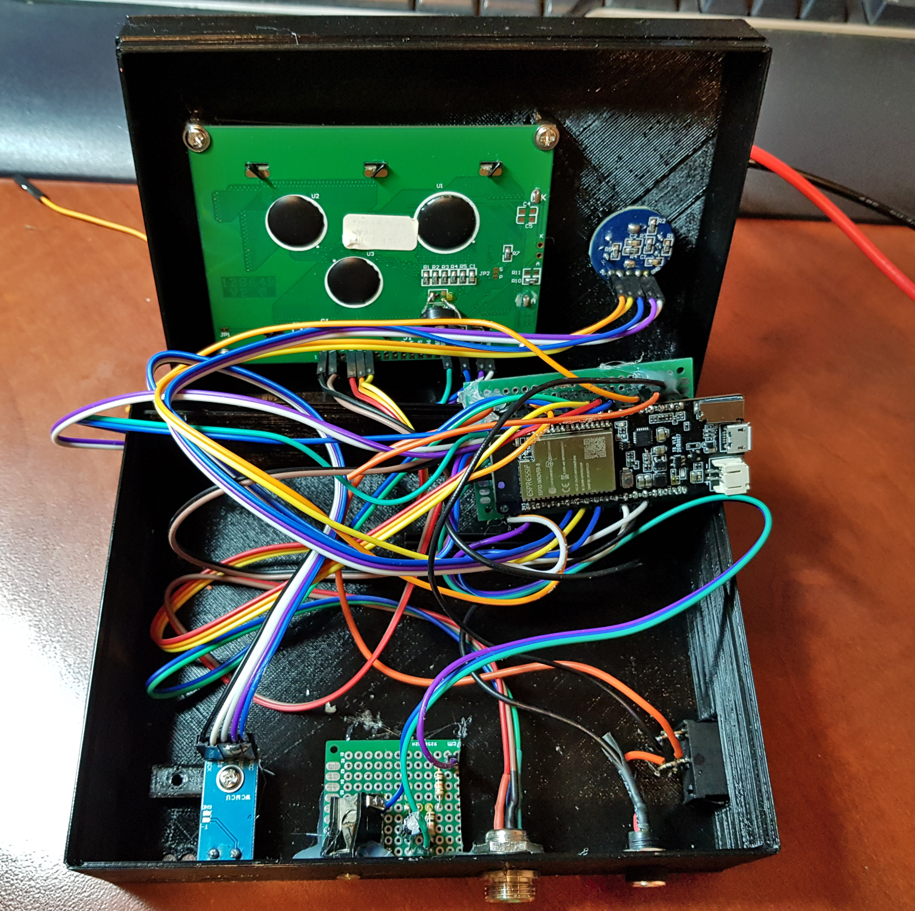
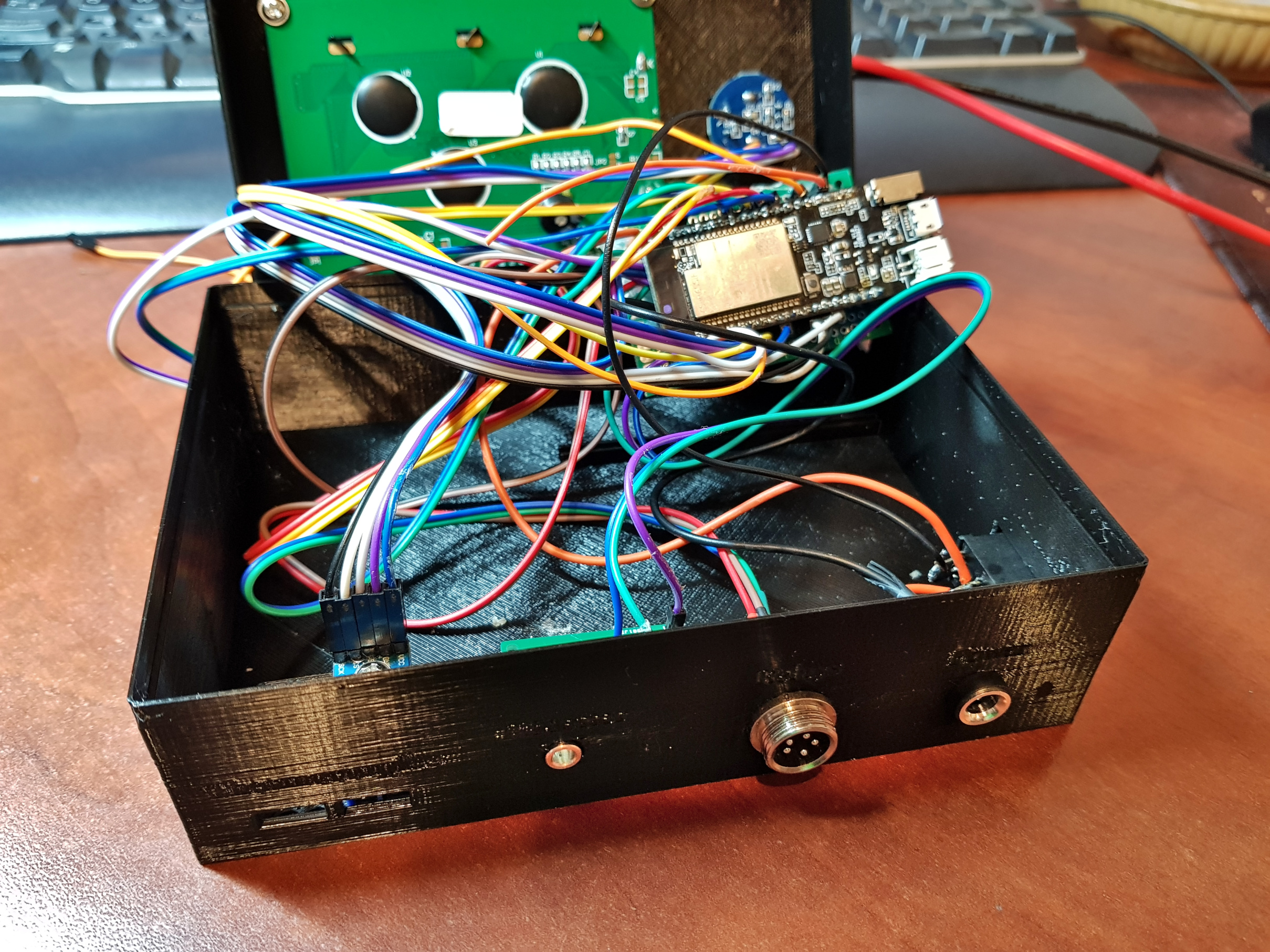
I thought about creating dedicated PCB for it, but it probably would require double side one, and so far I’ve been only making one side PCB on my CNC mill. Other problem I’ve seen was the WiFi antenna on TTGO board. With single PCB for all components, It would be shielded either by PCB or LCD or wires. This board does not have external antenna connector (some other does). So I’ve decided I’ll put ESP32 board separately and at 90deg angle close to the plastic case. This way signal should be not blocked anyway.
I’ve also utilized GX12 socket and plug – this are smaller sisters (or brothers) of GX16 I’ve been using on my CNC machine. We need just 4 wires for relays (GND, 5V, ESP PIN, SSR PIN) – but I had only 5 ping plug – so one is left alone.
Wire connections: 1- red (+5V), 2 – blue (GND), 3 – white (SSR), 4 – yellow (ESR).
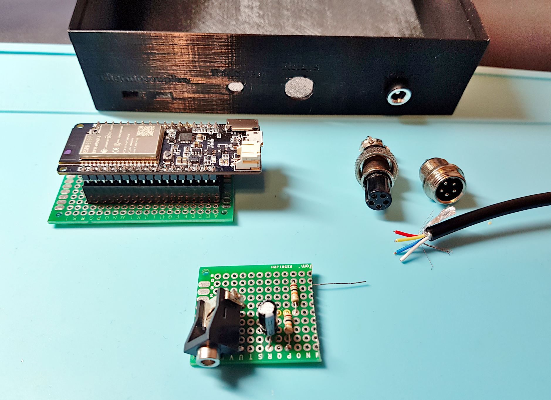
On the photography you can see back of printed case, ESP board on PCB, mentioned GX12 socket + plug and small PCB with passive components and a mini jack plug for power meter.
Printable case to download is available on Thingiverse.
Below you can see all the components (well – almost all – one MAX is missing since I had two different kind and wanted to put two identical PCBs – waiting for new one) inside the case.
From the left there are two MAX31855, power meter mini jack, GX12 socket for relays and power input 5V. On the right there is a power switch BUT this is not to enable ESP32 but to cut the connection to VIN pin – so I can connect safely it with USB to my computer.