First of all, it’s not full and proper howto – since I haven’t documented all the steps. It’s more like a key points guide for myself, when I’ll have to do it again 🙂 Never the less it should be quite useful for anyone struggling to do the same.
Why remove battery?
Since it will be all the time plugged in to power, battery would be charging and discharging all the time. This will kill the battery and could make it bulge or blow. Yet I still don’t get it, why it’s not designed to use only USB power, when connected and battery fully charged (same with laptops). Anyway, to make it safe, we need to get rid of battery.
What tablet to use?
First I wanted some Linux based (or Windows – and install Linux on it) – but variety of those and prices of new one, was not encouraging. So I was stuck with Android (let the google be cursed for what it did with it).
- I wanted at least FHD display (for good quality of HA dashboard)
- It should be IPS for good view angles, and sadly not Amoled, since it will display most of the time the same pattern and this is not good for it
- It should have decent front camera – for movement detection
- It should be possible to open
- And it have to be rootable
- quite new APU would be nice, to have HW acceleration of video decoders for camera views
So my first tablet was N-One NPad Plus – it’s under 100EUR 2K tablet with aluminum case. It was good because the case was closed with latches, not glued, and there was official firmware available, so rooting would be easier.
Sadly, when I wanted to buy another one (for second floor) it was completely out of stock… so I had to find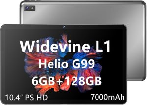 something else. I’ve found even cheaper LincPlus T3 tablet, but I guess it won’t be available long. Contrary to NPad, this had no firmware available and was glued 🙁
To open it, you have to use slick pry tool in quite steep angle under the screen, but push it more inside then under the screen – and go around screen, with suction cup pulling it up. It’s not that hard, and doesn’t require to use heat.
Next you have to unscrew two screws holding clamp on battery and screen port.
Tablet won’t run (it will start, but power off itself quickly) without thermistor (or just 10k resistor) on battery temperature line. But since all connection on the PCB are so tiny, it was extremely hard to solder to it and not rip off traces. So I cut of the battery BMS with connector from battery (under yellow kapton tape) and soldered +/- wire to solder joints on BMS board, leaving thermistor as it was.
I’ve made a hole on back of the case to move out wires for power supply.
Power
I’ve checked and it’s working well with 5V power supply (yes I know battery is 4,2V – but tolerance is higher – yet I don’t recommend it, since I don’t know if this wont have negative impact in the long run). It’s working on 5V/2A charger, but when connected to desktop power supply, tablet was able to crash when even 4V/6A limit was set – plain charger won’t cut off power when stressed, like bench power supply, but to remedy power spikes – I’ve added 1F 5,5V super capacitor inline. And it’s working fine.
Android, battery, charging…
Old ways of determining, if the battery is charged or not, was to just measure it’s voltage and extrapolate charge level. So if you use old tablet, with around Android 6 (don’t know exactly) – everything below doesn’t matter. But newer devices, measure current flow out and to the battery, when it’s charging and this way knows how much power has left. Because of this, even when battery is removed and tablet is powered with power supply, battery level will be dropping until 2% (or close to it) and Android will power off device – despite it doesn’t have to do it.
Of course we can’t simply ask Android not to do this and trust us, we know what we are doing. As usual the only way to change battery levels is to get root privileges, and of course Google knows better we shouldn’t do this (that company really sucks).
Rooting…
The easiest way is to use Magisk, it’s also beneficial because it has starting scripts – which we can use to disable battery daemon at startup.
But every permanent root requires to modify the kernel image or add files to root device and most common way to do it, is to extract it from original firmware made for updates etc. Sadly Linc tablet doesn’t have those and even despite company replied to my email, they said they won’t provide the image.
So we can use DSU (Dynamic System Update) to boot temporary Android OS with root privileges, to be able to copy boot.img and patch it with Magisk.
Prior to this, you have to switch Developer mode and Android, unlock bootloader, and then use this guide to copy boot.img from the device.
Next step is to install Magisk, patch boot.img and install it with fastboot. If you are brave enough, you can use my boot.img already patched with Magisk (it will work only on LincPlus T3 tablet).
Magisk script
Finally we have to create a boot time script to set the battery level and preferably disable the power daemon.
I’ve used the “dumpsys battery” command to spoof battery being 100% and charging, but it’s not the best way, since in background, charging daemon still count discharge and it will show less and less after reboot.
So add a file to “/data/adb/service.d/”
:/ $ su
:/ # cat /data/adb/service.d/update_battery_level.sh
sleep 20
echo "1" >/sys/devices/platform/soc/10026000.pwrap/10026000.pwrap:mt6366/mt6358-gauge/FG_daemon_disable
/system/bin/dumpsys battery set level 99
/system/bin/dumpsys battery set status 2
/system/bin/dumpsys battery set ac 1
Find in the /sys the FG_daemon_disable file (it’s different for android version and device) – and turn it on by setting it to 1. This is enough, and will set battery to 50% and won’t discharge it. If you wish to change charge level – dumpsys can be used for this purpose. But because it’s available in later stage of booting – what’s why I’ve put “sleep 20” on the beginning.
Don’t forget to add +x right on the file.
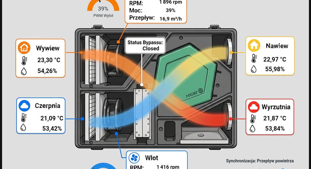
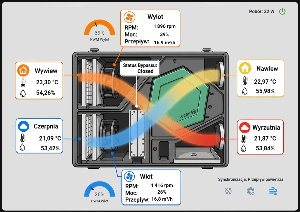 YouTube. Teraz (połowa 2026r.) przyszła pora na jej zamówienie i instalacje. W przeciągu dwóch lat sporo się zmieniło i pojawiły się modele z EPP (polipropylen spieniony) oraz stali kwasoodpornej. Wybór padł na EPP ECO (nie mam pojęcia co dopisek ECO oznacza). Cena tez znacząco wzrosła – planowałem 6k zł, wyszło 9k zł.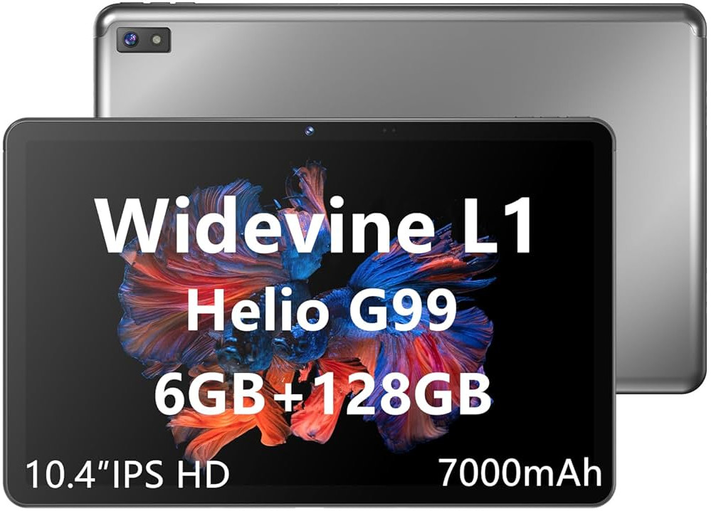
Recent comments